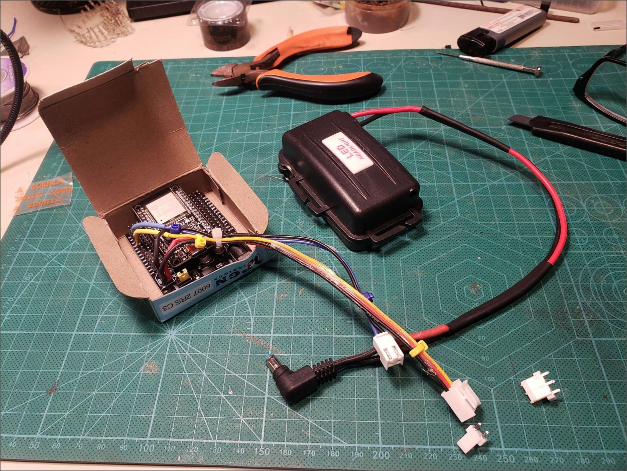
Mark I was a dev board wrapped in a weatherproof LED headlight case with a leather pouch. Mark II is a purpose-designed ABS enclosure with a 2" touchscreen showing a live GearSense dashboard. Same concept. Completely different presence.
The hardware arrives
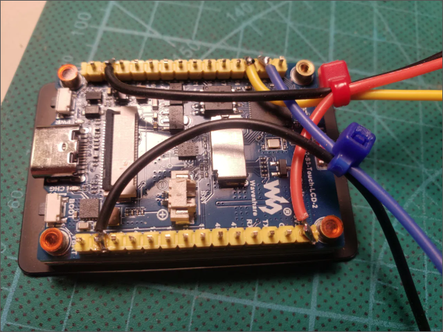
The Waveshare ESP32-S3-Touch-LCD-2 is a capable board: ESP32-S3 processor, 8MB PSRAM, 16MB Flash, a 2" capacitive touchscreen, onboard battery management, and a CS8501 hardware protection circuit. It showed up with the factory demo running — display sharp, touch responsive, battery reading 3.86V on arrival.
The 2000mAh 103450 LiPo batteries arrived the same day. Six print iterations to get the case right — tolerances, fitment, cable routing. By the sixth, everything landed where it needed to.
The case
The enclosure is a single-piece PLA print: 62mm × 41mm × 25mm outer. The battery fits cleanly alongside the board — no dividing wall needed, the geometry just works.
Cable strain relief is zip ties — looped through holes in the case walls so the wires can't be yanked out from outside. Simple, reliable, costs nothing, and already in the parts bin.
The front face is angled for handlebar ergonomics. The USB-C cutout is accessible without removing the lid for charging. First print needed minor dimensional tweaks — nothing unexpected on a first print. The design is still evolving: a third cable egress hole and a removable back cover are in the next revision. PLA now, ABS once the geometry is settled.
Wiring — the detective work
The GPIO assignments on the Waveshare board aren't fully documented for our use case. The factory examples are the ground truth. A grep session through the factory source files turned up what we needed.
The interesting find: GPIO5 is the battery ADC — but it's not broken out on the headers. It's an internal connection. That means battery monitoring comes for free, no soldering required. We would have found this eventually; finding it early saves a rework.
| GPIO | Wire | Function | Note |
|---|---|---|---|
| 4 | Blue | PAS cadence input | Camera pin — camera not used |
| 6 | Yellow | Wheel speed KY-003 | Camera pin — camera not used |
| 5 | — | Battery ADC | Internal — not on headers |
| 17 | — | Throttle DAC output | Phase 3, reserved |
Colour convention settled: Red = 3.3V, Black = GND, Blue = PAS, Yellow = wheel speed. The M6 connectors ordered for sensor leads, M8 for the throttle — different sizes mean different connectors can't be swapped by mistake in the dark on a wet trail.
The connector architecture
The throttle override solution avoids any permanent modification to the bike. An M8 1-female-to-2-male splitter taps the throttle line: one output passes straight through to the existing throttle, one comes from the GearSense DAC on GPIO17.
The control logic is deliberately conservative: the physical throttle always overrides GearSense when the rider twists it harder. The brakes override everything — that's hardwired in the BAFANG controller, not something we need to implement. GearSense fills the gap when the rider isn't actively overriding. Fully reversible, plug-in, no splicing.
The LVGL battle
Getting the LVGL toolchain working took longer than the wiring. The Library Manager installs LVGL 9.5.0 by default. The Waveshare BSP is incompatible with LVGL 9. Downgraded to 8.4.0. That fixed the build — until it didn't.
The next failure was a missing # — specifically #if 1 in lv_conf.h had become if 1. A single character. The compiler was entirely confused. These are the bugs that teach patience.
The BSP function signatures weren't in the docs in the form we needed them. Found by reading the factory source directly:
Each compile got further than the last. Methodical peeling of the onion — this is what embedded development actually looks like. Eventually the example compiled and ran. Then we wrote the GearSense firmware from scratch.
Mark II firmware v0.1.1
Written from scratch using the correct LVGL 8.4.0 three-argument API. The dashboard shows what matters: the current gear (large, centre-screen), cadence Hz, wheel Hz, the computed ratio, battery voltage, and state.
State machine: STOPPED / RIDING / COASTING / PEDALLING. Serial output in Mark I CSV format for backwards compatibility with the analysis scripts. Deep sleep kicks in at 3.2V battery for hardware protection (the CS8501 handles the hard cutoff; the firmware adds a graceful shutdown above that).
The money shot
Where we came from, and where we are.
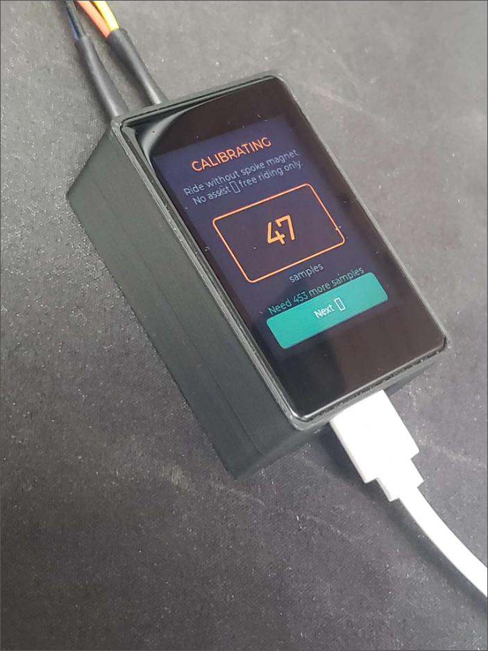
That's the proof made physical. Mark I told us the concept worked in data. Mark II tells you it works by showing you a screen.
A picture is worth 1000 words.
Paul O'Rorke, on seeing the working display
Loading…